Reblogged by cstanhope@social.coop ("Your friendly 'net denizen"):
Researching inductor parasitics, I found this cool manuscript by radio amateur David W Knight. To visualize the E-field in and around coils, they used a gas discharge tube! Even if you're not up for the math, check out the PDF linked below for a few more cool pictures 😄
https://g3ynh.info/zdocs/magnetics/appendix/self_res/self-res.pdf
Attachments:
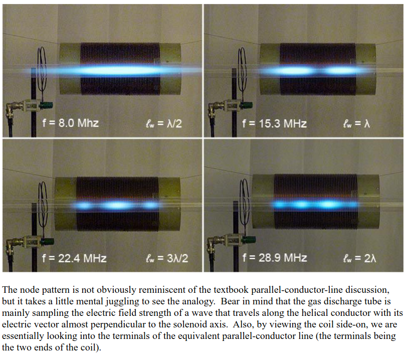
- Four pictures of a large, 10 cm diameter demonstration coil wound on a plastic core. The coil has about 100 windings made from very thick wire. Centered in front of the coil, aligned with the axis of the coil, is a long transparent mercury vapor gas discharge tube. Each of the four pictures has text with the excitation frequency of the coil, and in each picture, the gas discharge tube shows glow with a different notal pattern. At 8 MHz, there is one node, whose sides extend about half the length of the coil beyond its ends. At 15.3 MHz, there are two nodes symmetric to the center of the coil, extending about a quarter of its length outside of the coil. The nodes are skewed towards the coil's center. At 22.4 MHz, there are three nodes that are almost entirely within the coil's length, with the middle node being apprximately twice as long as the outer nodes. At 28.9 MHz, there are four nodes, with the middle two being about twice the length of the outer two. (remote)